Working with Shackles
Select the correct type and WLL of shackle and WLL for the particular application. If extreme circumstances or shock loading may occur, this must be well taken into account when selecting the correct shackle. Please note that only load rated shackles conforming to applicable standards shall be used for lifting applications. Never use “hardware store” type shackles.
Shackles should be inspected before use to ensure that:
- all markings are legible;
- the body and pin are both of the same brand and type;
- the body and pin are both of the correct size;
- never use a safety bolt type shackle without using a securing pin;
- the pin, nut, cotter pin, or any other locking system cannot vibrate out of position;
- the threads of the pin and the body are undamaged;
- the body and the pin are not distorted or unduly worn;
- the body and pin are free from nicks, gouges, cracks and corrosion;
- shackles may not be heat treated as this may affect their WLL;
- never modify, repair or reshape a shackle by machining, welding, heating or bending as this will affect the WLL.
Assembly
Ensure that the pin is correctly screwed into the shackle eye: tighten it hand-tight, then secure it using a wrench or suitable tool so that the collar of the pin is fully seated against the shackle eye. Ensure that the pin is of the correct length so that it penetrates the full depth of the threaded eye and the collar of the pin seats against the surface of the shackle eye.
Incorrect seating of the pin may be caused by a bent pin, too tight fitting thread or misalignment of the pin holes.
Do not use the shackle under these circumstances. Never replace a shackle pin except with one of the same brand, type, make and size to ensure the shackle maintains its original WLL.
Make sure that the shackle is supporting the load correctly, i.e. along the axis of the shackle body centerline.
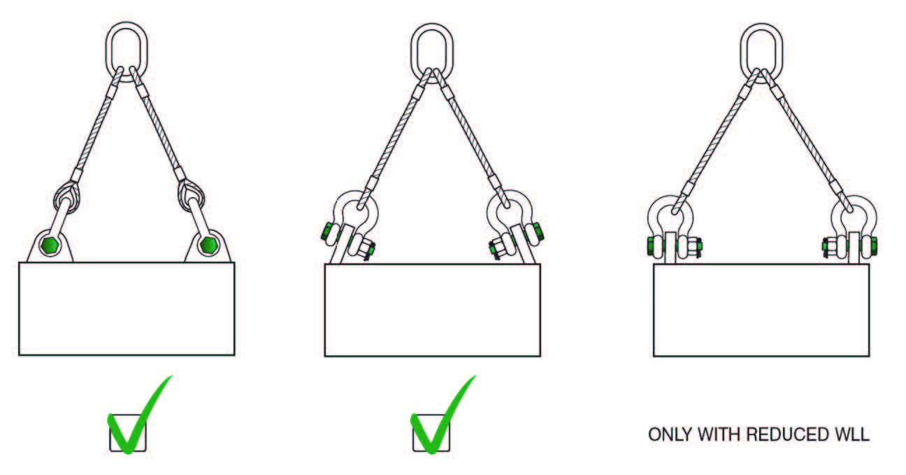
Side loads
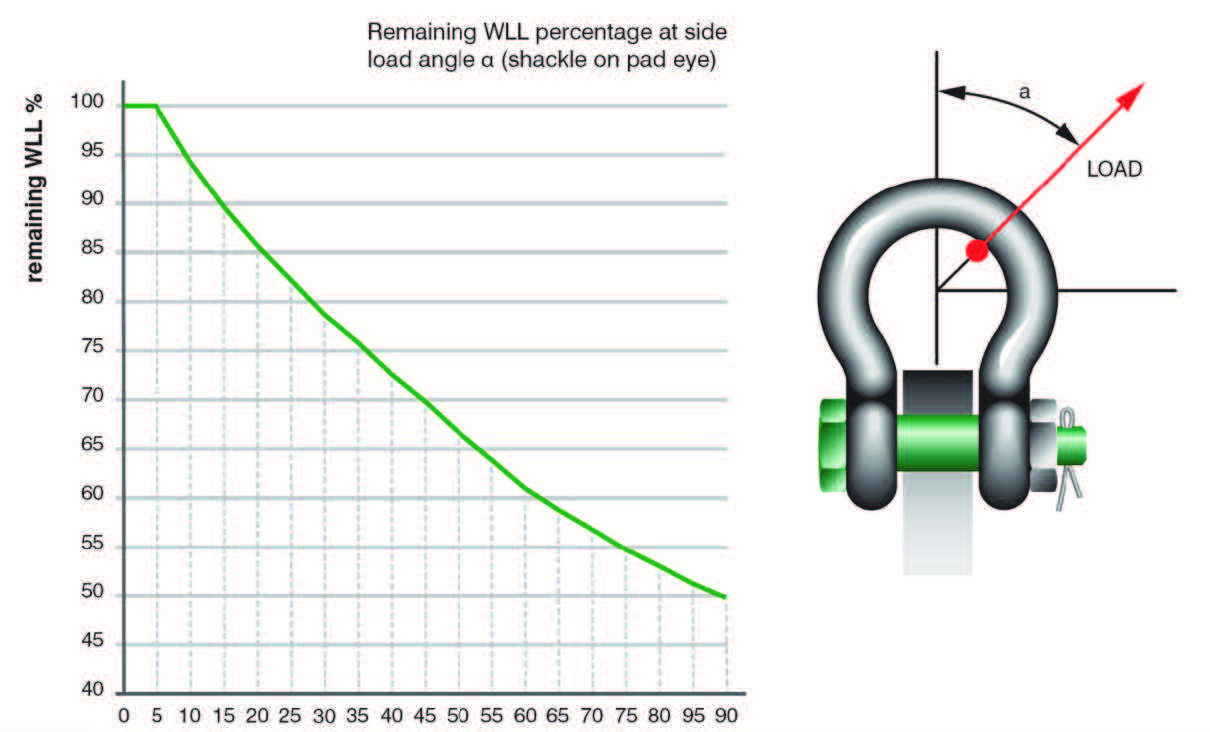
Side loads should be avoided, as the products are not designed for this purpose. If side loads cannot be avoided, the WLL of the shackle must be reduced.
This graph is valid for all Green Pin® shackles, except P-6033 (Wide Body Sling shackles). If you want to apply a side load on a Green Pin® Sling shackle, Please contact Unirope Ltd.
In-line lifting is considered to be a load perpendicular to the pin and in the plane of the bow. The load angles in the graph represent the deviating angles from inline loading.
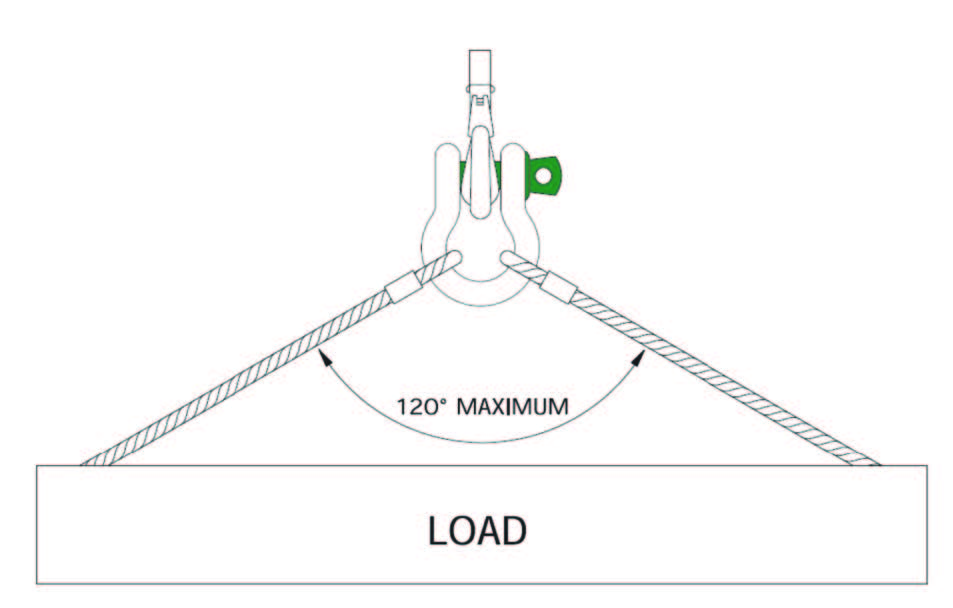
When connecting shackles to multi-leg slings, consider the effect of the angle between the legs of the sling. As the angle increases, so does the load in the sling leg and consequently in any shackle attached to that leg.
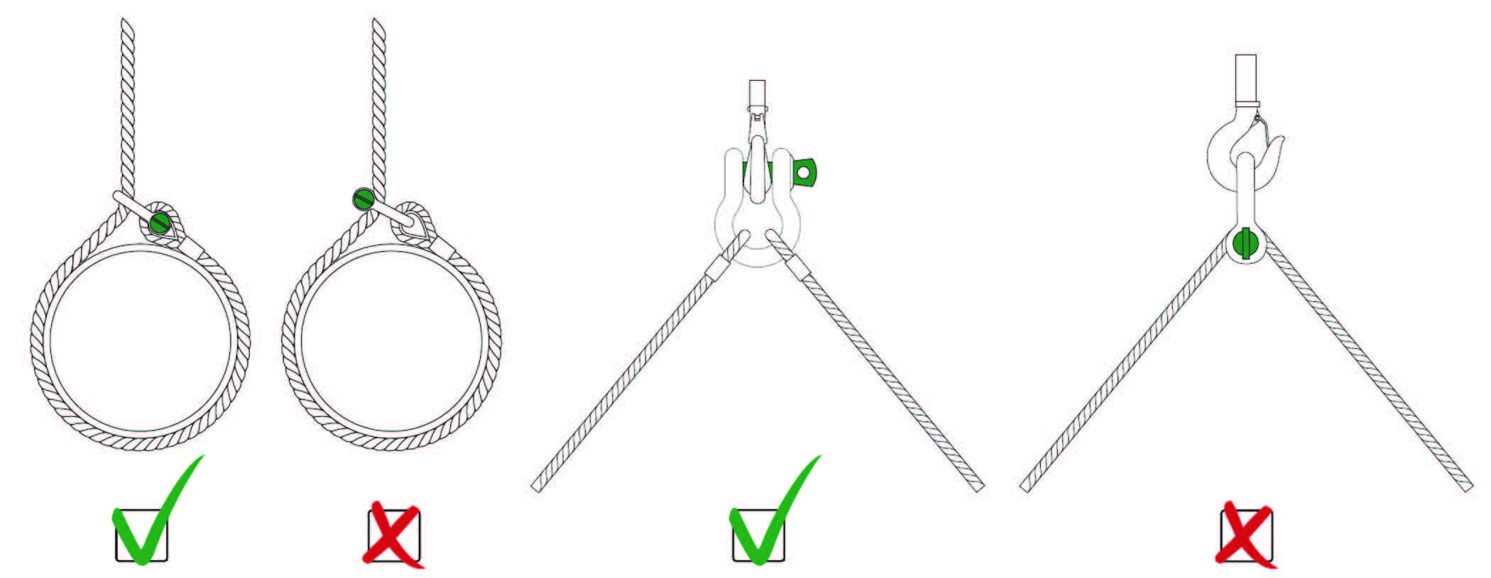
When a shackle is used to connect two slings to the hook of a lifting device, a bow type shackle must be used. The slings must be connected to the shackle body, and the shackle pin must be placed in the hook. The angle between the slings should not exceed 120°. If the sling legs are loaded equally the shackle may be used to the full WLL.
Side loads
To avoid eccentric loading of the shackle a loose spacer may be used on either end of the shackle pin. Do not reduce the width between the shackle jaws by welding washers or spacers to the inside of the shackle eyes or by narrowing the jaws, as this will affect the WLL of the shackle.
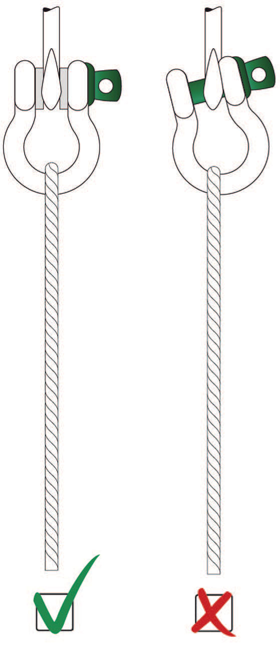
Avoid applications where the load moves over the shackle pin; the pin may rotate and possibly be unscrewed. If moving of the load cannot be avoided, or when the shackle is to be left in place for a prolonged period or where maximum pin security is required, use a shackle with a safety bolt, nut and cotter pin.
Point Loading
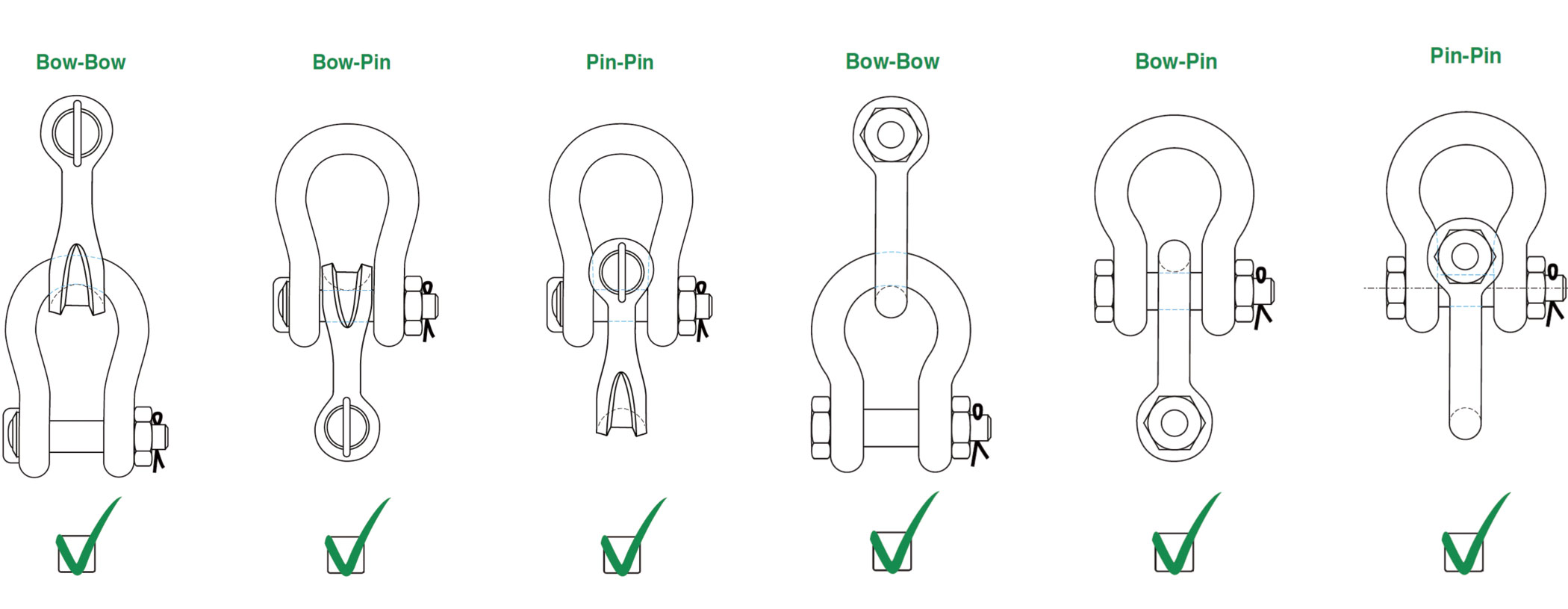
Shackles are used in lifting and static systems as removable links to connect (steel) wire rope, chain and other fittings. Most of the times the load bearing component that connects to a shackle is of a rounded shape. Point loading of shackles during lifting operations is allowed but the minimum dimension of the rounded component to be lifted should be equal to or bigger than the bow size of the shackle being used. The maximum load of the configuration is limited by the component with the lowest WLL.
Increasing the contact area by using bigger diameters and/or pad eyes can be an advantage. Sharp edges should be avoided. Green Pin® shackles can also be used in below configurations. The maximum load of the configuration is limited by the component with the lowest WLL.
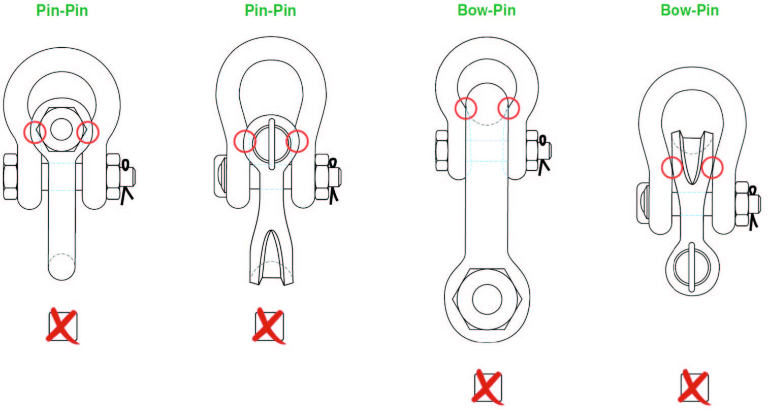
Pin-Pin configuration:
When the shackle eyes touch and the pins do not bear properly, the configuration should not be used.
Bow-Pin configuration:
When the shackle body of the inner shackle touches the shackle eyes of the outer shackle and body and pin do not bear properly, the configuration should not be used.