Hoist Ring Installation Information And Quality Standards
 |
- Select the proper Hoist Ring for the job. Do not attempt to apply more than the rated load capacity. The load capacity is stamped on the Hoist Ring.
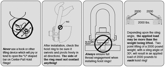
- Drill and tap the workpiece so that the hoist ring bolt is installed perpendicular to the surface of the workpiece. Countersink the tapped hole to prevent “swelling” of the top thread when the hoist ring bolt is torqued. The workpiece surface must be flat, providing complete contact for the hoist ring bushing.
- Do not use spacers between the hoist ring bushing and the workpiece surface.
- When installing in soft metal, such as aluminum, the minimum effective thread engagement should be two times the diameter of the thread. When installing in steel, thread engagement should be 1-1/2 times the thread diameter.
- Always tighten the bolt to the proper torque value, which is stamped on the Hoist Ring.
- Loosening of the bolt may develop during use. Re-tightening to the required torque must be done whenever the bolt loosens. The proper tightening torque is stamped on the Hoist Ring.
- When lifting, apply force gradually. DO NOT APPLY SHOCK LOADS.
- For through-hole applications, be sure that nut/washer are the same quality grade as the Hoist Ring.
- Periodic visual inspection and pull testing is recommended as damage can occur from improper usage.
|
| Quality Standards
Assembly Data
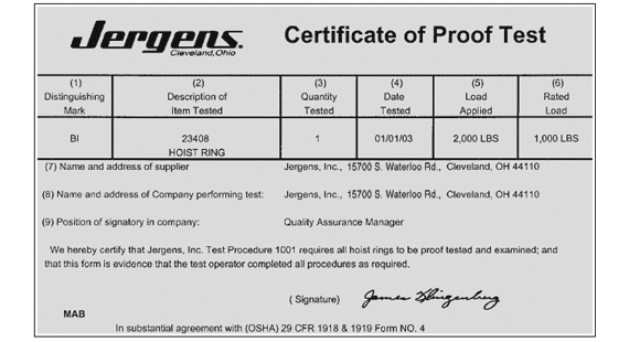
- Traditional Center Pull and Side Pull hoist ring assemblies are pull-tested and certified to 200% of rated load capacity and stamped with identifying date code.
- All hoist rings are designed for 5:1 strength factor.
- Hoist rings are color coded for easy identification: gold washer denotes inch sizes, silver/clear blue washer denotes metric sizes.
- Finished assembly is black oxide plated (with the exception of the washer).
- The Jergens name or logo is prominently displayed on assembly for identification of original manufacturer.
- Special plating or marking is available upon customer’s request.
- Proper warning label is affixed to each clevis.
- Proof load testing, magnafluxing, heat treating and material certification are on file at Jergens, Inc.
- The finished hoist ring product is individually boxed.
- NOTE: Specifications for side pull style hoist rings are identical to center pull style with the exception that the clevis is of precision cast alloy material which is serialized and conforms to X-ray specifications.
|
|
Load Bearing Member Components
|
Individual certificate of proof-test accompanies Center-Pull and Side-Pull Traditional Style hoist rings in final packaging.

|


